|
During firmware development we needed emulation of
module function in order to prove correct operation. This page
describes the various forms of hardware we've used since the beginning
of our effort. We call these our "Stepping
Stone" hardware platforms.
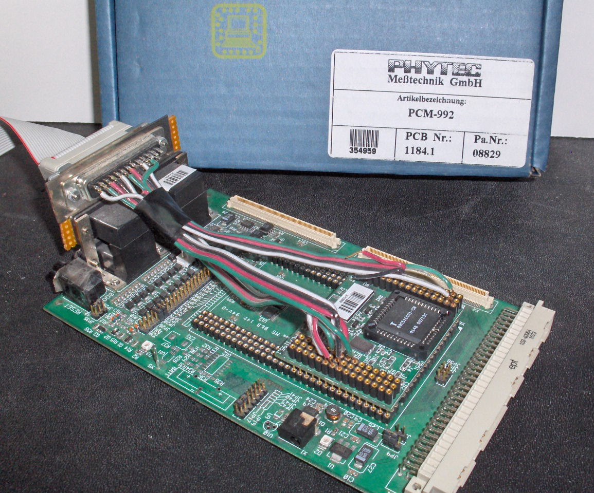
Test Hardware #1 - PhyTec Board
|
PhyTec PCM-992
Our first test hardware was purchased not built. Oct 2002 when we
started the CAN-Do! firmware effort it was easier to start with the
T89C51CC01 processor on this board for some of the tests. It contained
the exact same processor so we could try out code and exercise it
without depending on working hardware in the Widget. At this time
(when we first started) we still did not know how to control the
peripherals on the Widget, so having this board allowed us to get to
working code before we had fully checked out our Widget hardware. It
gave us an alternative context in which to run the new code in order to
prove that we coded it well. The last attempt we made to use this
board was to wire it to a parallel port so we could emulate byte-pipe
traffic. This turned out to be complicated and we found ourselves
limited to uni-directional traffic over this lash-up.
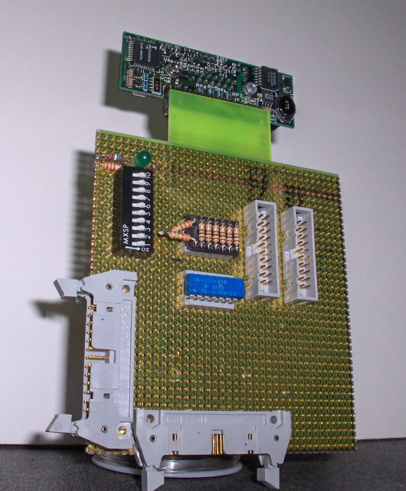
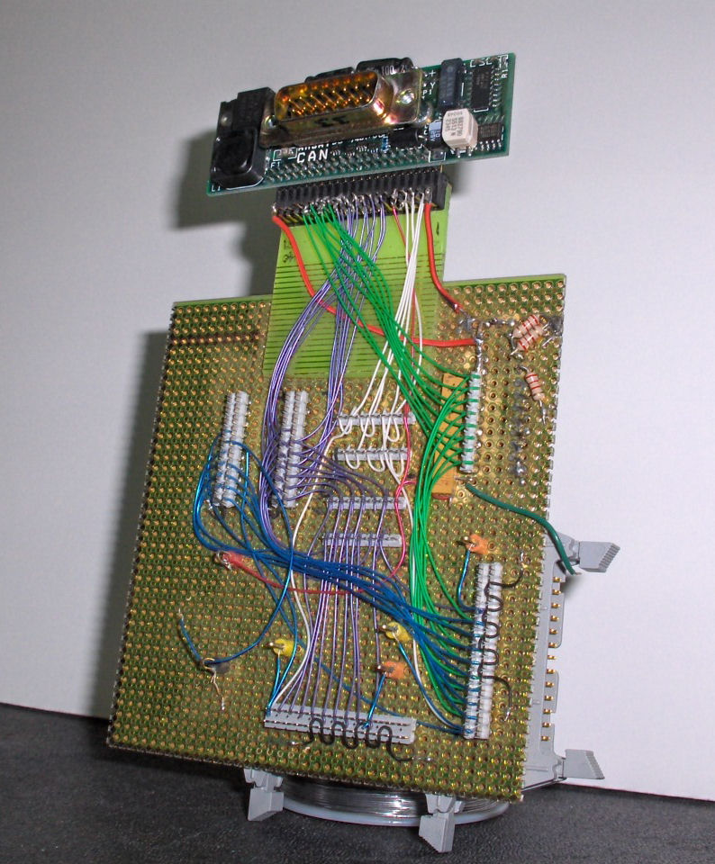
Test Hardware #2 - Wire-Wrap Board
|

|
Wire-Wrap
w/Widget - Front / Back
As soon as our first batches of Widgets (100 in all) started arriving
in Colorado Springs we needed to exercise all of them and all
their capabilities. (Digital inputs, Digital Outputs, Analog Inputs,
Power On/Off control, etc.) Bdale built the "Wire Wrap" board
based on mix of concepts by John Conner, Bdale and Stephen.
Features of this board:
- A resistor network gives us a fixed set of values for each
of the analog inputs. These values are evenly spaced throughout the
analog sensor range. This makes it easy for us to see if any of the
analog channels are not working as expected.
- 10 Dip switches provides control over
- All 8 digital inputs (switch for each.)
- Enable / disable of resistive load so we can test
current sensor
- An LED provides easy visibility of switched power
output
- Two connectors for an Agilent Logic Analyzer (guess who
one of us works for ;-) are used to monitor all the digital
inputs and outputs
- Two connectors at bottom left for parallel cables so we
could drive the inputs, read the outputs from our earlier parallel-port
control software
During Widget initial testing Stephen drove the CAN bus
writing tools and flashing while Bdale drove the Logic
Analyzer and the dip switches. Bdale stimulated things and
read results. We traded off logging of our results.
Randomizing the DIP SW patterns always kept us on our toes
;-).
We tapped a Radio Shack DVM into our CAN/Power cable so we
could measure Widget current draw during the testing as
well.
schematic: TBA
developed by:
Bdale Garbee, KB0G, John Conner, NJ0C, and
Stephen Moraco, KZ0Q
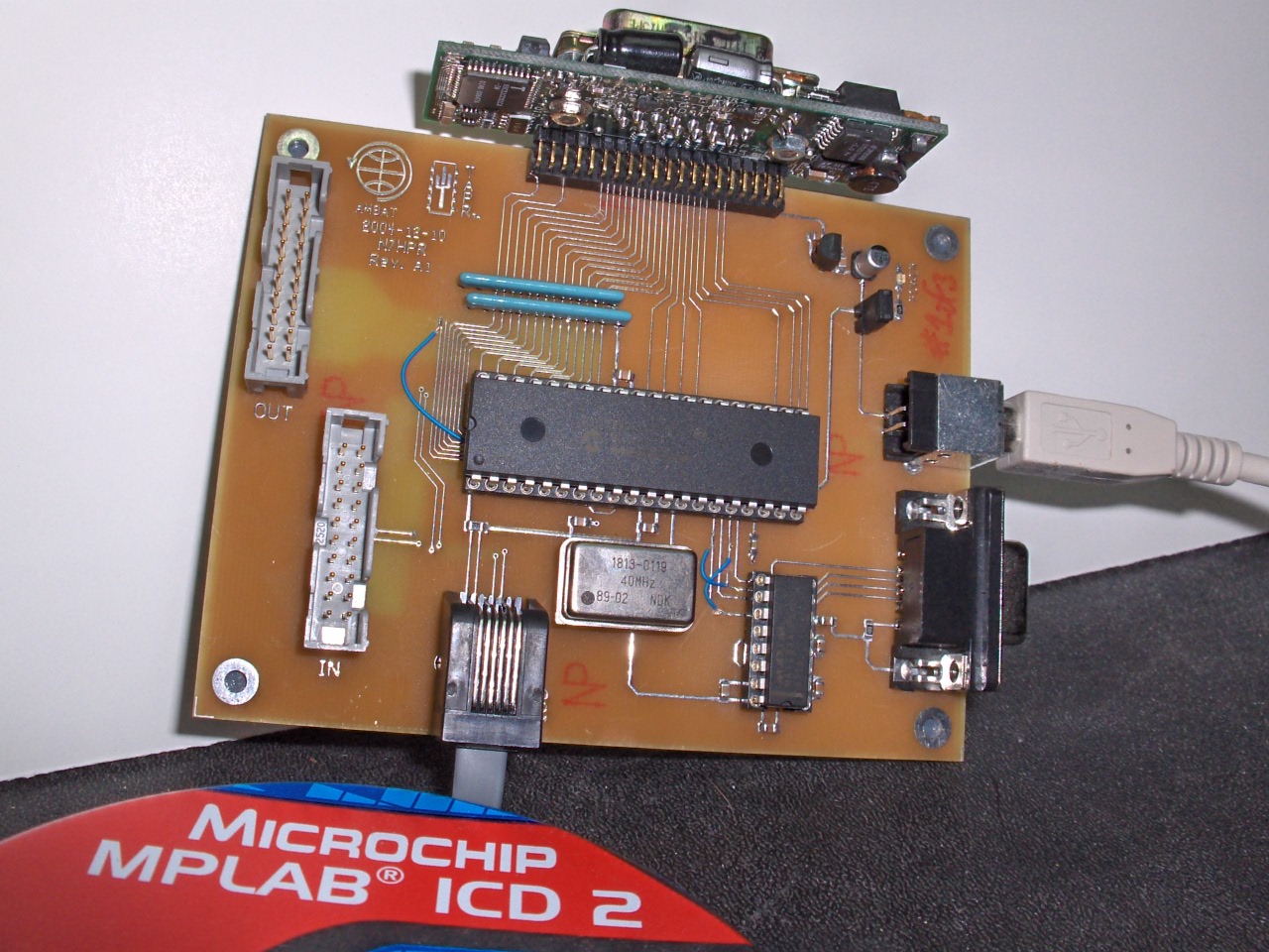
Test Hardware #3 - PIC-based Pipe-Mode Emulator
|
PIC-based
PipeMode Emulator w/Widget
As soon as we stepped into development of the pipe-mode firmware it
became clear that this could not be made to work unless we had specific
hardware. At our AMSAT annual conference in 2003 we asked for help
building such a board. Steven Bible, N7HPR volunteered to help.
We developed a specification from
which he developed and built the board. After getting enough basic
firmware working, he handed the whole thing off to Stephen (around Feb
2005) to complete the firmware and get on with developing the pipe-mode
firmware. This board worked well. We developed and released the first
working byte-pipe firmware using this test environment.
Features of this board:
- PIC-based board with onboard FLASH memory for code
- ANSI C development environment
- ICD-2 in-circuit debugger / firmware loader
- Functions controlled via serial port command interface
(communicated with running board via hyperterm windows application
- Two connectors for an Agilent Logic Analyzer are used
to monitor all the digital inputs and outputs
- Powered from Widget or from USB cable
- Socket mounted crystal allowing us to upgrade processor
speeds
Experience with the first implementation (we now have
three of these) exposed a limitation in hardware (PIC
speed). However, that was quickly addressed by replacing the
crystal and the PIC with faster versions. The great thing
about using the PIC was that we simply moved to a pin/code
compatible faster version with hardly any more work than a
re-compile of the code for the new PIC microprocessor.
This test board still serves well today when working on byte-pipe
mode testing. Our next immediate effort is to accomplish the
1st
implementation of the Pipe-mode file transfer protocol.
This board may
be a candidate for that testing.
developed by: Steven Bible,
N7HPR
from specification:
Pipe-mode Emulator Test Fixture Spec
schematics:
PIC
-based Pipe Emulator Schematic and Board Layout
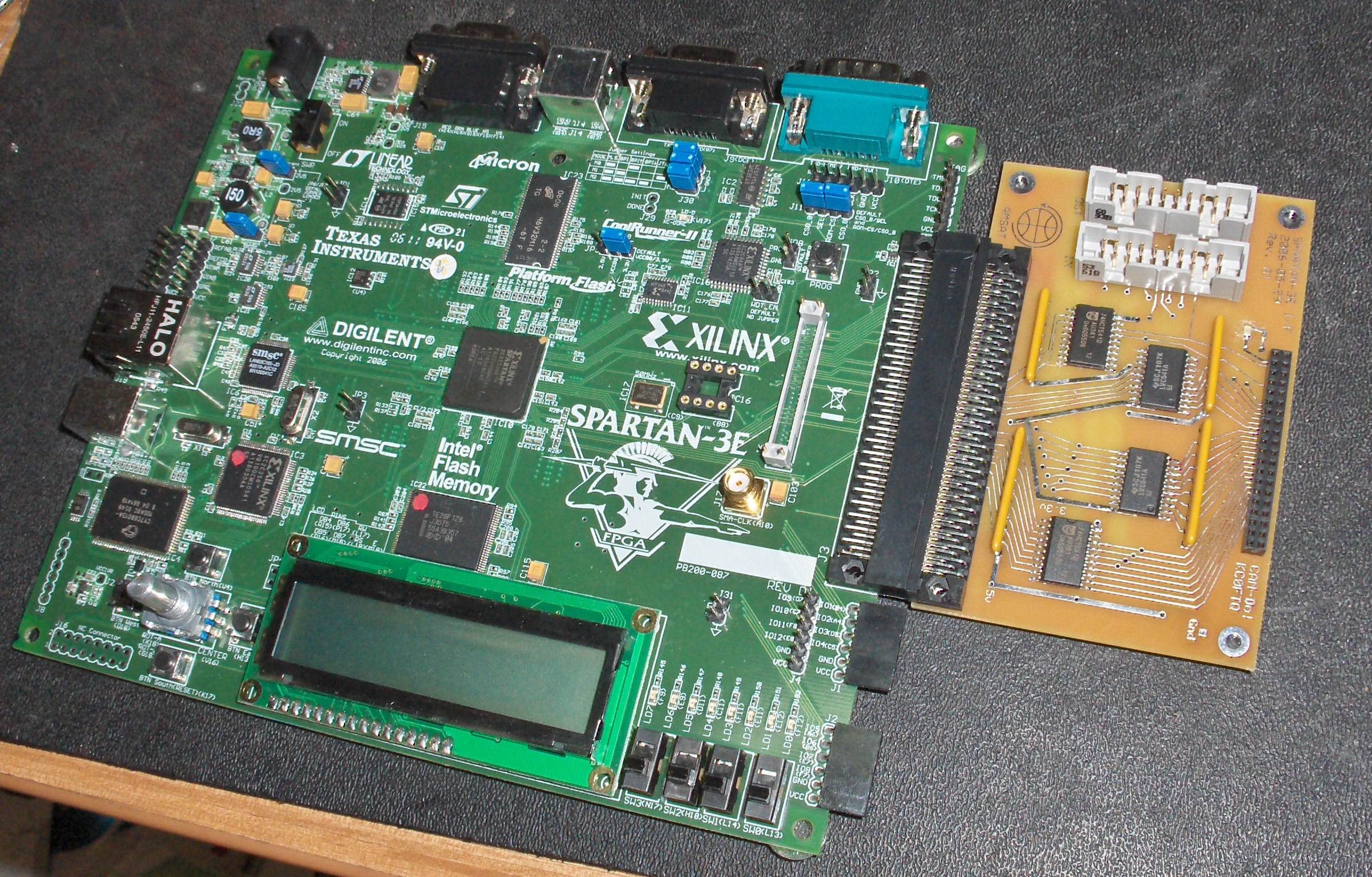
Test Hardware #4 - Spartan3E Xilinx Demo Board with Widget Adapter
|
Spartan3E
w/Widget I/F Board
As I was wrapping up my first implementation of the pipe-mode
firmware for the Widget, I became concerned that we had not tested the
pipe mode function at best speed. Also, in working with the
Arizona Star Camera team, I saw a number of issues. I found that I needed to better understand what it took to build hardware to interface
to our byte-pipe mode Widget. Around the time I identified this need I
was asked to better understand Xilinx implementation of circuits for my
real work. I decided to marry these two needs by purchasing the
demo board and then designing and implementing a Widget interface for
the board. Lyle Johnson, KK7P, kindly guided me through this, my first
ever, PCB implementation.
Features of this board:
- Xilinx-Spartan3E demo board
- Xilinx tool-chain supporting VHDL/Verilog implementation
with support for embedded cores (PicoBlaze, MicroBlaze,
and PowerPC)
- Two connectors for an Agilent Logic Analyzer are used
to monitor all the digital inputs and outputs
- A single high-density Soft-touch Pro connector for a Logic
Analyzer
- Pipe handshake lines are LED-monitored, w/two extra LED
outputs for misc. use
- Many switches, push-buttons, LED, Ethernet, USB, etc.
available for use in design
Testing with this board provides confidence that the
current pipe-mode firmware can run with very fast module
implementations without negatively affecting Widget
performance. This proves that Widget firmware implementation
is robust from slow speed module implementations through to
high speed module implementations.
In the near future with this board, we will be experimenting with using
the GNU compilers for building the file-transfer module side first
implementation.
main board: purchased
Widget I/F board developed by:
Stephen Moraco, KZ0Q
specification, Schematics and
Board Layout:
Spartan3E
Widget I/F Test Fixture Spec
Example top-level Xilinx Design:
Simple pipe
auto-responder
Test Hardware - The future?
These boards each have served us well. However, if we are to
develop more Widgets then we will have to build a basic functional test
platform. Today, each time we prepare a batch of Widgets for use
or prepare them even for flight, we find ourselves running the entire
test suite by hand using the Wire Wrap board. This is time
consuming as it is an entirely manual process. Our best
improvement here would be to automate the testing and recording of
results along with contrasting the behavior of tested Widget against others
in the batch.
Now you have a feel for how involved we have been in developing
and testing the Widget firmware through 1st implementation. You
can see that we've been investigating all aspects of performance and
function. We have been using custom hardware to make this testing as
robust as we practically can.
If you have questions, suggestions or would like
further
information feel free to contact me.
- Stephen KZ0Q
|